ZXQ2003, ZXQ2004 electric valve intelligent locator is the industrial microcontroller core of the intelligent signal acquisition and control system, compact, and can choose to install in the junction box of the electric actuator or fixed outside a DIN rail, industrial instrumentation can directly receive4-20mADC or computer output signal (input signal type at the factory custom) with potentiometer feedback electric actuator supporting a variety of valves or devices for precise positioning operation on the corner of the electric actuator (or displacement) free calibration, while the output 4-20mADC of, actuator corner position (or displacement) feedback converted signal can be the key to accurately set the actuator corner position the lower limit value and upper limit values, locator 3key operation, nine LED lights can be displayed directly to the locator modal 4 digital LED display through the key switch valve bit to open the actual value, the valve position set the opening value, locator shell temperature, easy to operate.
● control accuracy: 0.1% -3.0% (adjustable) U4 parameters
● potentiometer can be accessed by the electric actuator feedback signal: 500Ω-10KΩ
● can receive an external control signal (DC) 4-20mA (1-5V ,0-10V, switch factory custom)
● Input impedance: 250 Ω;
● modify the U1 parameters can be set: the ① DRTA / positive action, RVSA / reverse action mode (2) the input signal is interrupted, "interrupt" mode-OPEN (open), STOP (stop), SHUT (closed)
● Optional: ① The SCR output (AC, 600V, 25A) (2) relay outputs (AC 250V, 10A) ◆ When ordering specify
● Output to actuator position signal: 4-20mADC low drift output corresponding to the actuator is fully closed to fully open, the signal completely isolate the input (optical isolation), the output load ≤ 500Ω
● Ambient temperature :0-70 ℃, humidity :35-85%
Have over-temperature protection function: Locator shell temperature ≥ 70 ° C, the locator stop opening and closing of the actuator control
● Dimensions: ZXQ2003 77mm (underside length) × 76mm (bottom wide) x 51mm (high); ZXQ2004 74mm (underside length) × 57mm (bottom wide) x 45mm (H)
● key free calibration input signal corresponding to the action of the actuator range (generally calibration for the electric actuator is fully closed, fully open position)
● You can set the upper and lower limit points
● actuator stall detection and control functions: to control the actuator stall last 3-4S, locator disconnect control output 1min; repeated measurement and control, stall exclude.
● You can set the accuracy of self-adjusting: the actuator in the course of their work, can not locate, and three times back and forth vibration locator automatic positioning accuracy down to 1/1000 (ie: the original accuracy of +1 / 1000), repeatedly adjusted to suitable control precision. Set the parameters for U0 (000.x)
● lock to prevent misuse
● Anti-actuator frequent start function
● with error code indicates the cause of the malfunction (E, 0X)
● Press the corner position of the input signal and actuator smart step to adjust the precise positioning

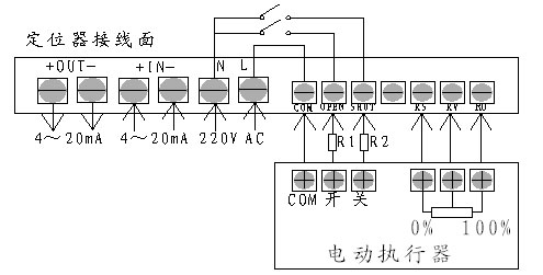
Reference the wiring diagram on the following figure meter terminals and instrumentation enclosure to connect the electric actuator and power connections, pay attention to the polarity of the connection in order to reduce the interference of the motor, should be electric actuator motor control lines and feedback signal line separate walkline; meter weak signal lines should be as short as possible, must use a longer connection should be used to shield the signal lines, the outer shield and the control cabinet enclosure is properly grounded.
Locator and electric actuators are connected by a seven-line connector, the locator GND terminal on the actuator housing and motor connections or vacant do not take; RO, RV, RS, respectively, then electric actuator feedback potentiometer three terminal where the wiper of the potentiometer RV access, RO connected between the actuator to open the action and the sliding arm resistance decreases continuously at one end, the RS is connected to the other end; SHUT, oPEN, COM, respectively, then the actuator servo motors, closed, open, COM terminal.
Note: In order to weaken the actuator start and stop when the current shock, usually in the "OPEN," CLOSE "respectively with the actuator in the" ON "," closed "indirectly 4Ω/5W the cement resistor (Figure under R1R2).
Note: the locator COM, OPEN, SHUT active output terminal, COM, OPEN, COM, the SHUT corresponding output voltage for the power supply voltage.


